Tuesday, July 6, 2010

Wichita Machinists, Disc Brakes, and Part 103 Ultralight Aircraft

Wichita, KS is the home of Belite Aircraft and also the Aircraft Capital of the World!

As home to a majority of general aviation aircraft (EG:  Cessna, Beechcraft/Hawker, Bombardier/Learjet, also Spirit Aerosystems and Boeing Military) with notable exceptions of Cirrus and Piper, Wichita has a diverse manufacturing community.   In particular, there are hundreds of small, medium, and large businesses which provide components to the major aviation companies.

Many (but not all) of those companies have been hurt badly by the aviation slowdown of the last couple of years.

This has been an opportunity for Belite:  we've been able to find a machine shop or two who are capable of providing us with very high quality machined parts for our Belite Part 103 ultralight aircraft.

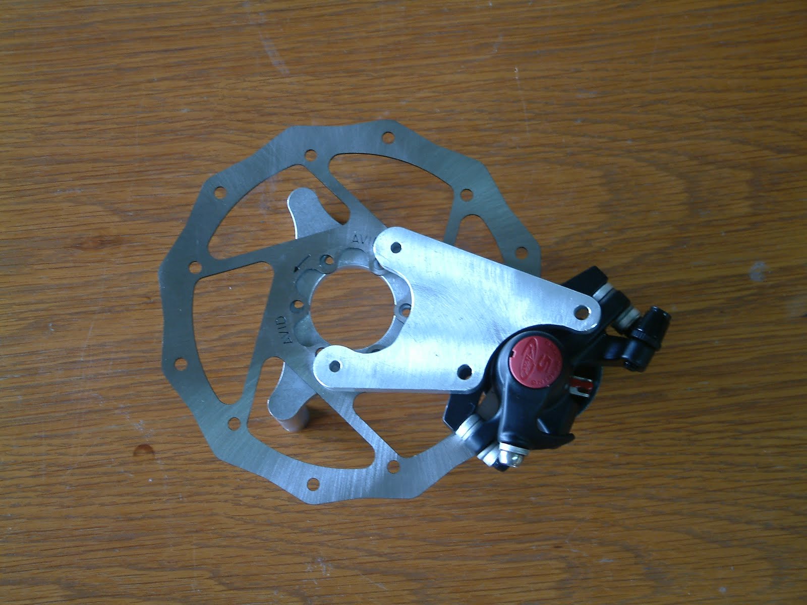
And tonight, I provide just one example:  our new disc brakes, which we are installing on our ready to fly and kit aircraft.  These disc brakes are composed of three major components:  a machined 'tripod' standoff, which works in conjunction with a solid steel 4130 chromalloy axle to attach to the brake rotor and to the wheel; a brake attachment plate, and, of course, a disc brake caliper/rotor assembly, which comes directly from the mountain bike industry as an OEM component.  It works great for our lightweight aircraft.

Here's what the assembled brake looks like (the brake cable is not attached in this photo) (also note the steel spring suspension):


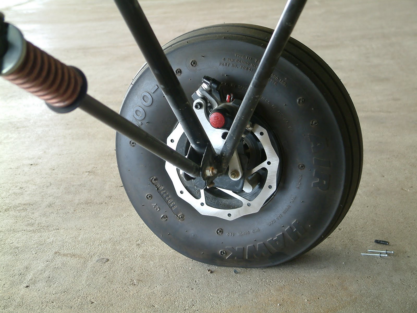
It's a very tight, neat looking arrangement.

The aluminum components are machined from solid billet: 6061T-6, which is a common aircraft alloy.

Let's take a look at each individual component.  Here's the standoff 'tripod':


And here's two more views of the same part:


This 'tripod is used to fix the brake caliper to the wheel.  It's designed to work with our 5 inch wheels, which are now the standard wheel on every Belite aircraft.

Another component is the brake attachment plate.  It's a simple part, and is very strong.  Here it is:


To make all of this work, we do need a disc brake rotor and caliper.  As I mentioned previously, our Part 103 ultralight aircraft are well matched to use a brake from Avid.  Here's the brake:


So let's stack all these parts up and see what it looks like.  You can see the 'Tripod' below the brake rotor:


And let's now put the attachment plate on top:


Obviously a few nuts, bolts, axles, and cables missing.  But hopefully, you get the idea.

Here's one more look at how it ends up on the aircraft landing gear:


Side note:  Look at that nice big fat 5.00 x 5 tire!

We sell these for $350 as a kit and $400 installed on our flyaway airplanes.  The kit includes left and right sides.  (pricing always subject to change without warning.)

You can find them on our Ready To Fly spreadsheet, and also on our Price Your Own Kit spreadsheet.

My thanks to my able assistant Gene Stratton for shooting these pics.

Friday, July 2, 2010

A great trailer for hauling an ultralight aircraft

How do you trailer an ultralight airplane?

A common question concerns trailering our Belite ultralight aircraft.  For long distances, nothing beats a covered trailer.  But for short distances, a boat trailer works great for hauling the aircraft between your home and the airstrip.  You just have to do a little work to make it work perfectly.

My friend, Terry Alley, bought a boat trailer and modified it to haul his Kitfox Lite around.  I recently borrowed his trailer to haul a Superlite from our hangar, over to my Church for a car show.  (And that's another story, how our airplane ended up being the only airplane at a car show.)

Here's a pic which shows the Superlite on the trailer. Note the trailering bar which are attached to the leading edge of the wing, down to the strut attachment point.  (This provides rigidity to the wing, so that it is not damaged while trailering.)  Also note how the ramps have been set at just the correct width to allow the plane to roll backwards and onto the trailer:


Here's a pic of the airplane on the trailer from the side.  Note that the trailer is exactly the correct length, so that the tailwheel is by the ratchet lever:


Here's pic of the aircraft from the front of trailer, looking back.  You can see a gust lock on the elevator/stabilizer on the right side:


The airplane is just a little long for this trailer, so the tailwheel springs have been disconnected, and the tailwheel twisted 180 degrees backwards.  The tailwheel fits into the steel channel which is part of the original trailer.  Note the ratchet drum (which isn't used for anything anymore) and also note the center 'V' channel which Terry mounted on the trailer.  This is for the tailwheel to 'roll up' the trailer as the aircraft is backed onto it.


After the airplane is loaded, the wheel ramps rotate up and are bungeed in place.  This locks the wheels and the aircraft onto the trailer.  Also note the wooden plank across the rear of the trailer.  This was put on the trailer so the aircraft tires would have a solid place to rest.


You can't see it here, but some straps are used on the other side of the wheel to lock the landing gear strut in place, so it can't roll at all.  I also use some extra bungees around the landing gear to the boat trailer, as good redundancy.


In this pic, you can see the red nylon straps.  You can also see our awesome steel spring landing gear on the Belite:


Don't forget to tie the tailwheel to the front of the trailer.

Also, don't forget to install solid gust locks on the rudder and the elevator.

And that's really all there is to it.  Trailering a FAR part 103 ultralight is easy; so is trailering any small experimental aircraft.  I hope this gives you some good ideas on how to make a great, inexpensive trailer for hauling your aircraft around town and out to the airstrip.

Sold the Kitfox Lite, Again

That pesky Kitfox Lite which I had for sale has been sold for a second time.  After the first buyer backed out, another emerged a few days later. 

The new buyer has instructed us to perform some upgrades on it before it is delivered.  Bigger tires, bigger wheels, better spring suspension, different engine.  All fun stuff!

Thursday, July 1, 2010

How to make a Carbon Fiber elevator which weighs less than 3 pounds!


I am planning to give a forum at OSHKOSH on how to make a Carbon Fiber elevator.  PLEASE PLAN TO ATTEND!  Thanks.

The Carbon Fiber elevator which is depicted here WEIGHS LESS THAN 3 POUNDS!  And it is stronger than steel.

Carbon Fiber offers benefits which make it vastly superior to 4130 chromalloy steel in many applications.  Careful design is required, though, in order to take advantage of Carbon Fiber's incredible strength and stiffness.  Belite's Carbon Fiber elevator upgrade swap is an available upgrade for any Belite (or Kitfox Lite replacement aftermarket) which will provide a lighter part with far higher strength and better aerodynamics.  This part is available in kit form for a price of $350 over the regular elevator.  (You can find it on our kit pricing spreadsheet here as line item #55.  Remember, this is an upgrade price over the steel elevator (which is separately priced at $399.95).  A straight purchase of this Carbon Fiber elevator kit is $399.95 + $350 = $749.95)

Our Carbon Fiber elevator is a direct replacement for the steel part.  It is made from several basic materials:

Carbon Fiber fabric wound tubing (for leading edge / torque spar)
Carbon Fiber extruded tubing (for trailing edge)
Steel horizontal stabilizer connect hardware (qty 2 -- connects to hinge points on horizontal stabilizer)
Central Steel section (connects to hinge point and to elevator push/pull tube)
Carbon Fiber ribs in various laminations from 3 to 6 layers of carbon fiber 3K cloth, over balsa core
3M 2216 industrial epoxy (amazing stuff)
Laminating epoxy
Dacron Fabric

Jumping to the finished part, here is what it looks like:


And here is how to make it:

1)  Ensure Carbon Fiber spar tube is exactly 92 inches long.  Cut with fine tooth saw to length.

2)  Debur, clean and slide the center steel assembly over the spar tube.  Epoxy in place with 2216 glue.

3)  Debur, clean and slide each hinge point over the tube.  Do not epoxy. 

4)  Cut each rib section using a band saw and supplied rib outline.  Cut front circle to match spar tube.  Leave rear portion extra long, excess length will be trimmed.  Carefully cut angle cuts on center ribs; also cut reinforcement segments. 

5)  Cut wingtip ribs and center ribs to exact length. 

6)  Cut trailing edges to length; you may leave them slightly long.

7)  Glue wingtip ribs and center ribs in place to main spar and trailing edges using 2216 glue.  At this point, you have a complete outline of the elevator.  Allow to fully cure (24 hours) before proceeding.  It is helpful to wrap around carbon fiber tube and ribs with masking tape.  This will force glue to exact shape and is easy to pull masking tape off after curing.

8)  It is now easy to continue fitting each rib to exact length requirement.

9)  Glue all ribs in place using 2216 glue.  Glue remaining hinge points in place.  Allow to fully cure (24 hours) before proceeding.

10)  Now all ribs are in place.  Sand excess 2216 off.  DO NOT sand into any Carbon Fiber.

11)  Reinforce all joints using carbon fiber cloth and conventional laminating epoxy.  This is easily done by laying the carbon fiber strip over the edge, with the elevator vertical, and painting on the epoxy.  It is helpful to do the leading edge, allow to cure, then flip the elevator and do the trailing edge.

12)  Trim excess cloth using either a dremel or a sharp razor blade.  If you use a razor blade, it is helpful to do it prior to full cure of the epoxy.

13)  Sand all Carbon Fiber cloth.  Remove every single sharp point.

14)  Cover using Stewart Systems glue and dacron fabric.

Here's the advantages:

a)  thicker profile allows aerodynamic shape
b)  lower weight, of course
c)  stronger
d)  impervious to rusting
e)  It's just plane cool!  Or is it plain cool?!

Here's some more detail pics.  Our kit includes plans and more assembly info.....